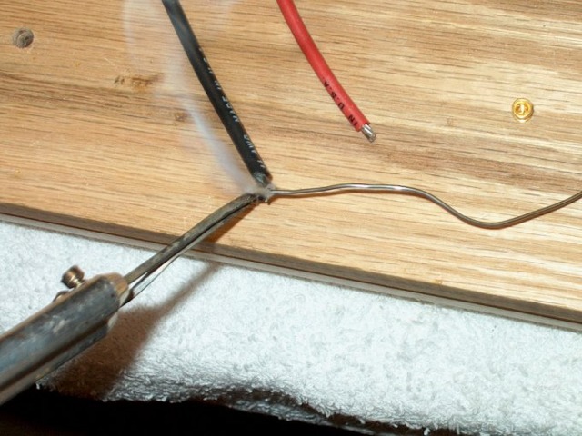
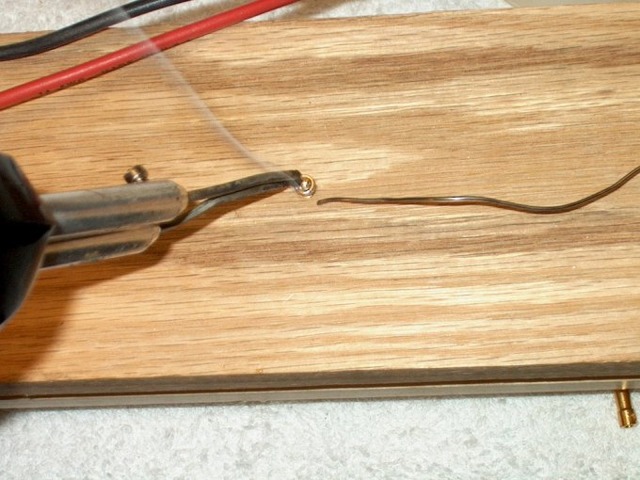
59 - Socket rear is pre-tinned and filled with solder.

60 - Wire is soldered to the 3.5mm socket.

61 - Both wires soldered.

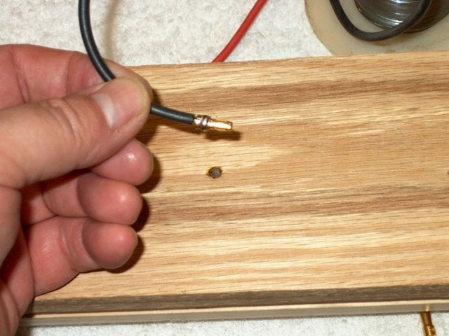
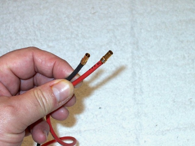
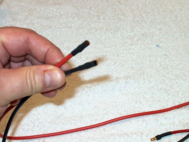
62 - Heat shrink tubing is added for insulation.


  63 - The three sockets are connected to the motor wires on the ESC, while the two 3.5mm plugs are installed on the battery wire. 64 - Heat shrink tubing is added to finish the sockets.
 
 
  65 - The battery harness is cut to 12" in length.  The fuselage is shown in the rear to show how the run would fit, from the fan/motor location on the right to the center of the battery compartment on the left. 66 - A Deans "Ultra-Plug" is soldered to the other end of the harness.
 
 
  67 - The entire assembly is connected and the fan is checked for balance. 68 - heat shrink is applied to the motor connector to insure they will not come loose.
 
 
  69 - Fan would not fit inside of the fuselage as the opening was not large enough. 70 - The fan was positioned over the opening and a pencil was used to mark the rear wing saddle area.
 
 
  71 - You can see where it was hitting... DO NOT FORCE IT IN as you can crack the ductwork.. 72 - Mark made from previous setup is shown.
 
 
  73 - A Dremel with a cutting wheel is used to rough cut the area. 74 - Then a Dremel with a drum sander is used to shape the opening.
 
 
  75 - The fan fits inside now and very little saddle was removed. 76 - Fan shown completely inside of the fuselage.


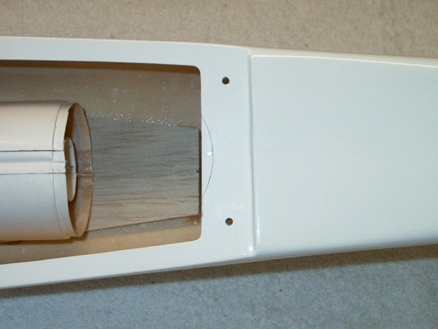
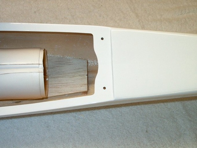
77 - Note the ends were also rounded, which "relieves" them and helps prevent cracking.

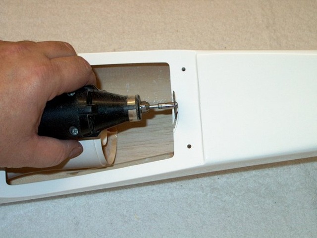
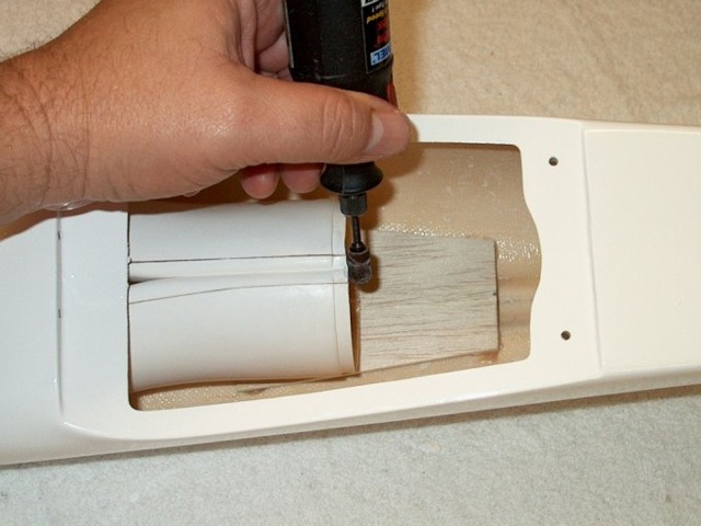
78 - A Dremel with a sanding drum was used to even up the ducting.

(NEXT PAGE)