![]()
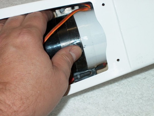

139 - Packing tape used to hold the exhaust duct in place.
140 - Exhaust duct installed.

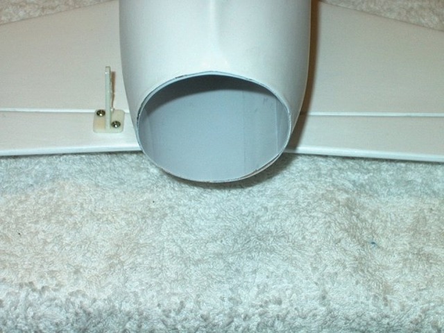
141 - End of exhaust area trimmed even with the tail cone.
142 - Exhaust finished.
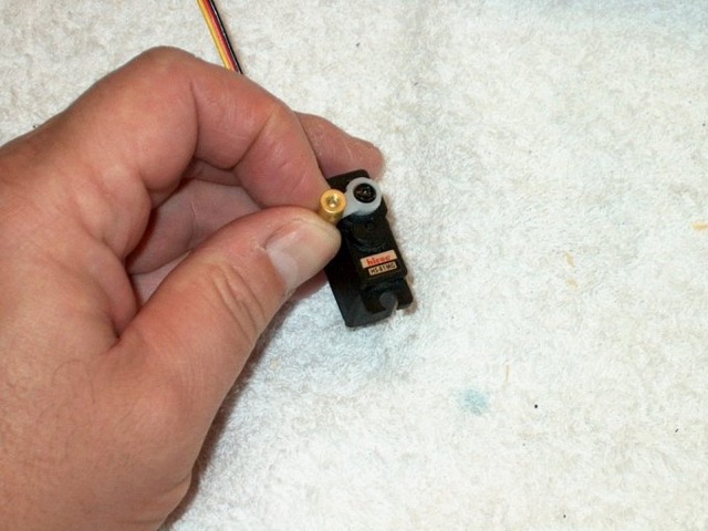
143 - The servo horn was installed and the EZ Connector supplied with the model was installed in the outer horn hole. The hole needed to be enlarged for the threads. Make sure it turns freely once installed and use Loktite on the threads.
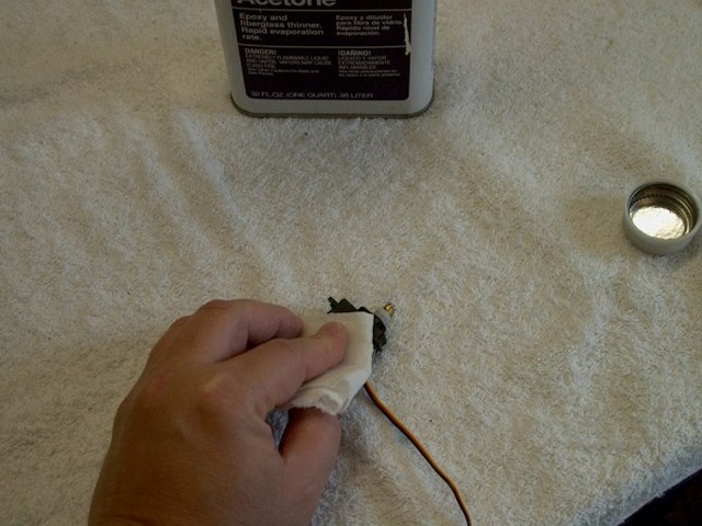
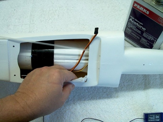
144 - Servo side is cleaned with acetone.

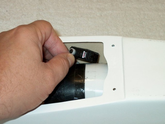
145 - Mounting tape is applied to the servo side.
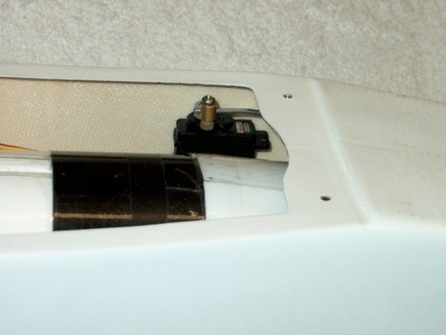
146 - Servo is then installed on the sidewall. Make sure you clean this area with acetone before mounting the servo.
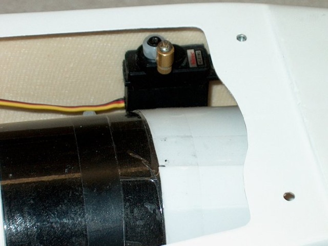
147 - Elevator servo installation completed. Note that the washers supplied with the gold connector were not used as they would have caused binding on the servo arm when rotating.
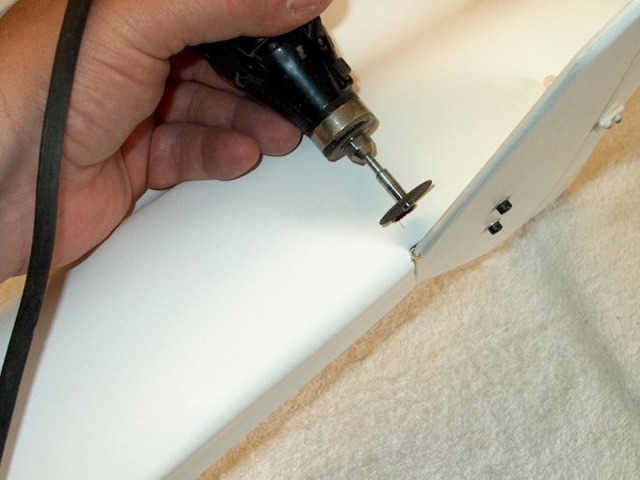
148 - Hole is opened on side of fuselage for the elevator control rod.
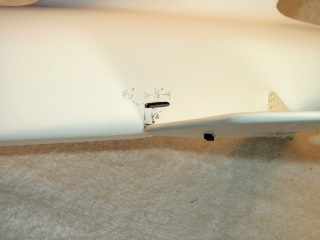
149 - Hole shown below... NOTE: It was extended to 7/8" in length later on during the build. It is 3/32" wide and the bottom is 3/8" above the horizontal stab.
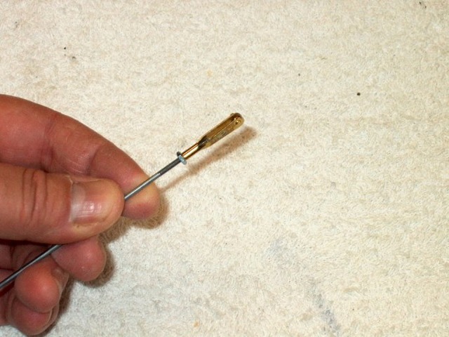
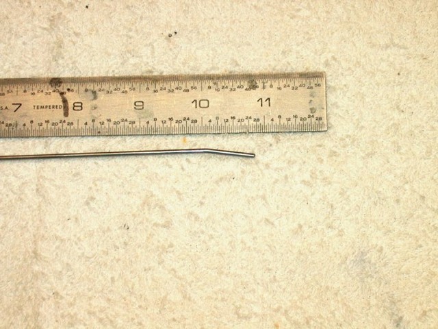
150 - Clevis installed on a new 2-56 x 12" long pushrod.

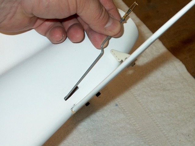
151 - Rod bent and shaped for opening.
152 - Picture shows rod shape and points to bend.
153 - End was slightly bent to align with the EZ Connector for the servo.
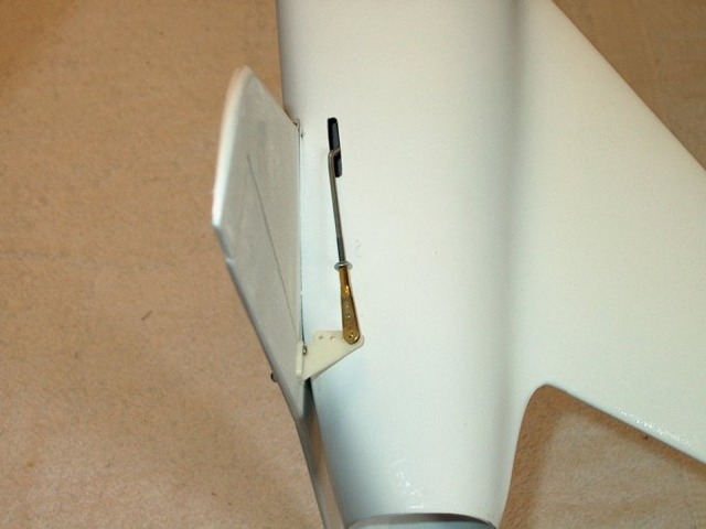
154 - Rod final installation.
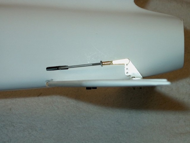
155 - Pushrod installed.
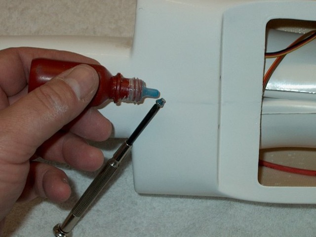
156 - Loktite added to EZ Connector set screw.
157 - Turn on your radio, then center the servo, center the elevator and tighten the screw.
158 - Inside of fuselage cleaned for receiver location.