![]()
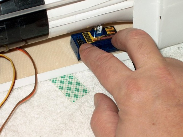
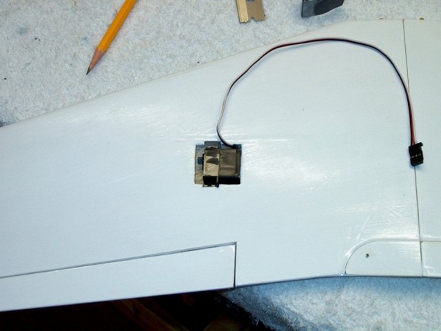
159 - Original receiver installed in the following location.
160 - In order to properly balance the plane at 90mm CG from the leading edge of the wing at the fuse, the receiver was moved back about 2" from the original location (as the pencil point shows.) This was done to allow for battery pack placement to balance.
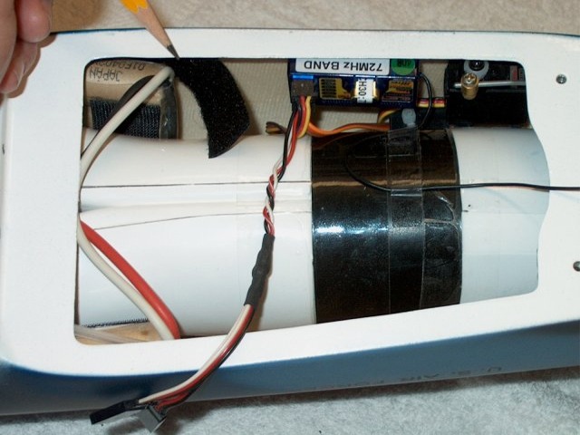
161 - Originally the antenna was installed in a tube and installed partially up in the nose...
162 - ... and the rest of the antenna out the back of the fuse. This was later found to produce glitching and changed.
NOTE: If you decide to install your antenna this way you must do a range check. We do not recommend you install your antenna this particular way for the Sniper.
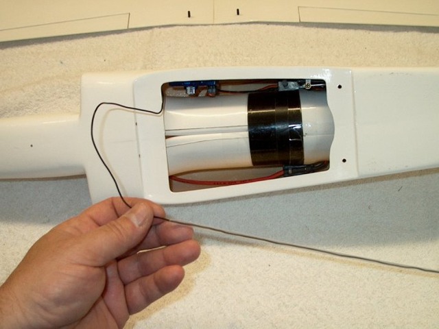
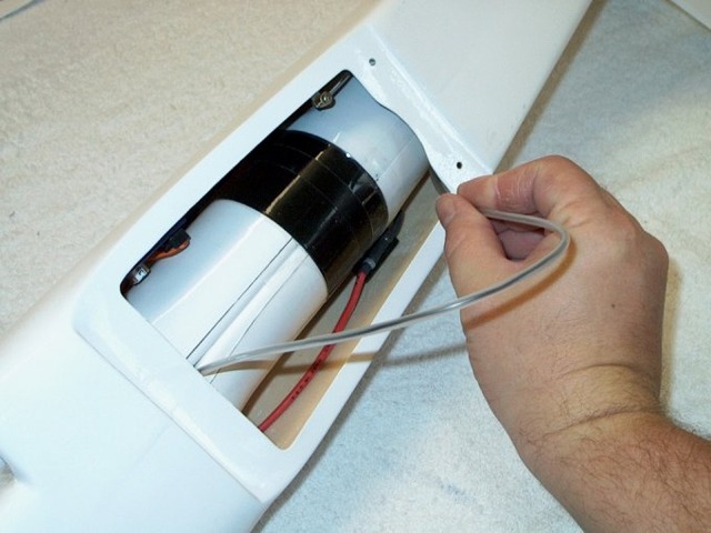
163 - The following is the recommended method to install your antenna. A range check is still mandatory, but based on Carl's maiden flight, this method seems to work best.
164 - Y-Connector added for aileron servo wires... build completed.
165 - Basic fuselage assembly completed.
166 - Aileron servo area was soaked with thin CA to strengthen, then sanded smooth.
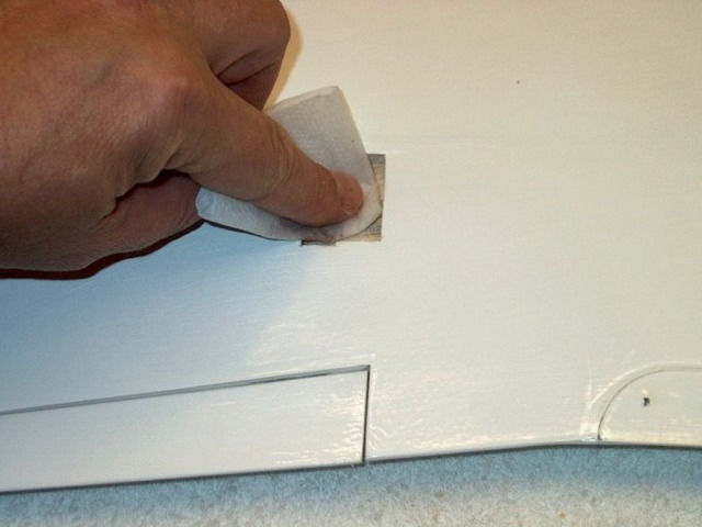
167 - Area cleaned with denatured alcohol.
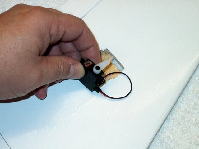
168 - Servo temporarily fit to cut horn slot.
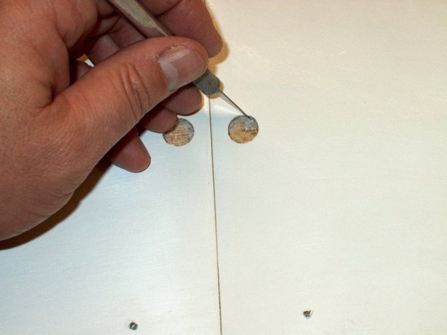
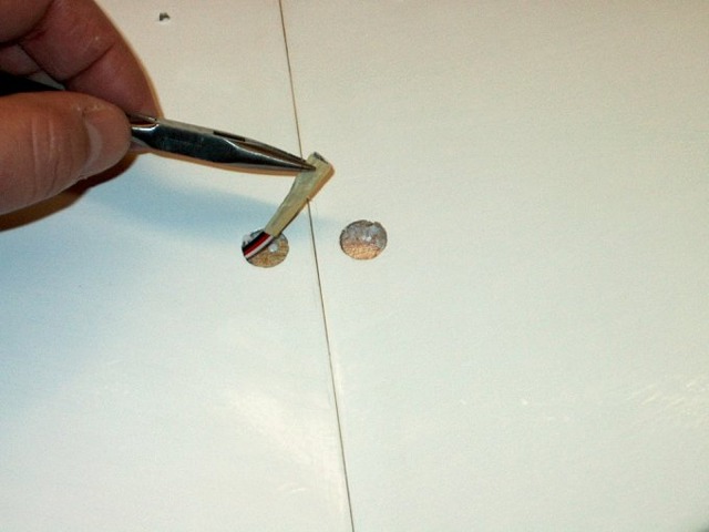
169 - Servo wire holes opened up in the wing.
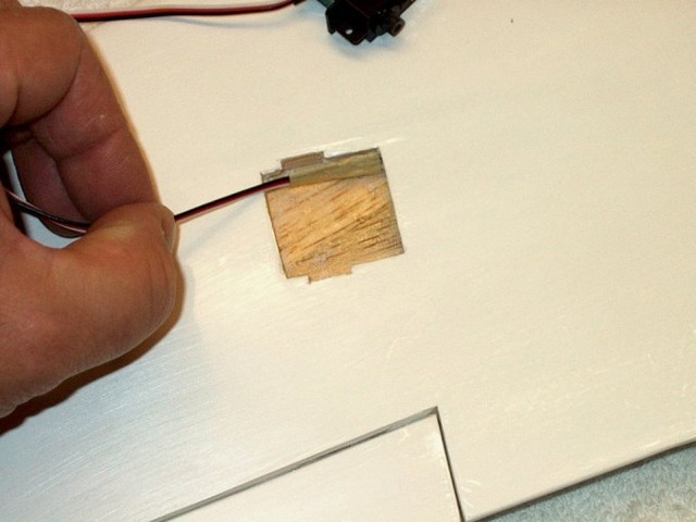
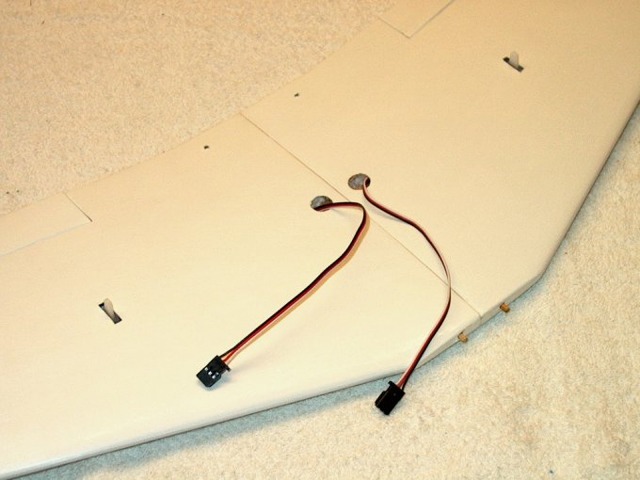
170 - Servo plug removed and wires run through pre-cut channel.
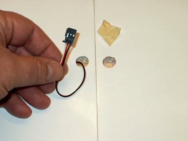
171 - Wire pulled throgh from aileron servo bay.
172 - Plug re-installed on servo wires.
173 - Servo arm installed.
174 - Servo cleaned with acetone and double sided tape added.
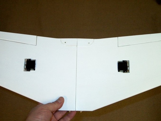
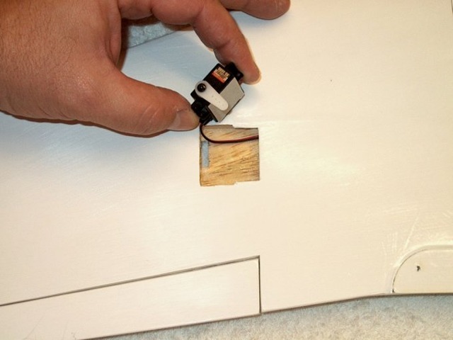
175 - Servos installed in both wings.
176 - Aileron wires exiting wing.
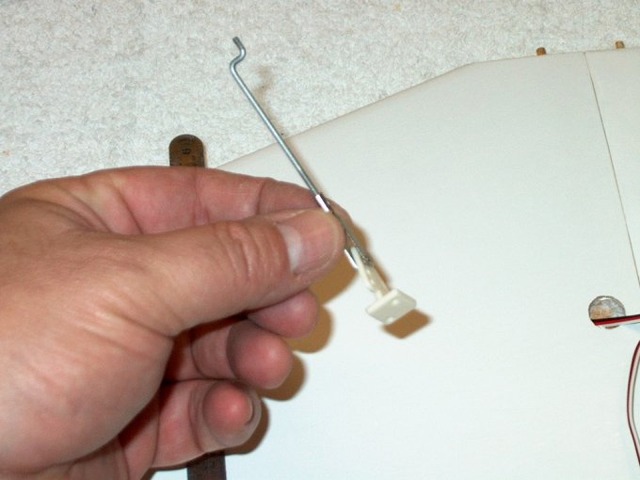

177 - Shaping the aileron pushrod. A Z-bend was used on one end.
178 - A ruler was used to align the pushrod while the aileron horn was installed.
(NEXT PAGE)